LVS Manager - User Guide
Welcome to the LVS Manager User Guide. This documentation helps users configure, operate, and monitor UDP-based SRT load balancing using LVS Manager.
Table of Contents
- Getting Started
- System Overview
- Navigating the Interface
- Dashboard Overview
- Accessing LB Configs
- Click on Rates
- Configuration Details
- Configuration Management
- Select All or Groups of Ports
- Editing Backend Servers
- Live Monitoring & Statistics
- Real-Time Backend Switch
- Connection History & State Events
- Creating a Load Balancer Configuration
- VIP (Virtual IP) Management
- Add Ports
- Edit VIP
- Bulk Edit VIPs
- Bulk Delete VIPs
- Backend Management
- Add Backends in Bulk
- Edit Backends in Bulk
- Delete Backends in Bulk
- Applying Configuration to Live System
- Advanced Operations
- Master/Backup Node Failover with Keepalived
- Pairing Nodes for Configuration Sync
- Port Mapping Capabilities
Getting Started
LVS Manager is deployed using a private Docker repository. Please contact your system administrator or support team for access credentials.
🚫 Manual source installation is not supported.
System Overview
LVS Manager provides an intuitive UI for managing multiple Load Balancer (LB) configurations backed by Linux Virtual Server (LVS) specialized for live UDP streaming (SRT/RIST), but capable to use TCP for other less effective video streaming protocols too.
Navigating the Interface
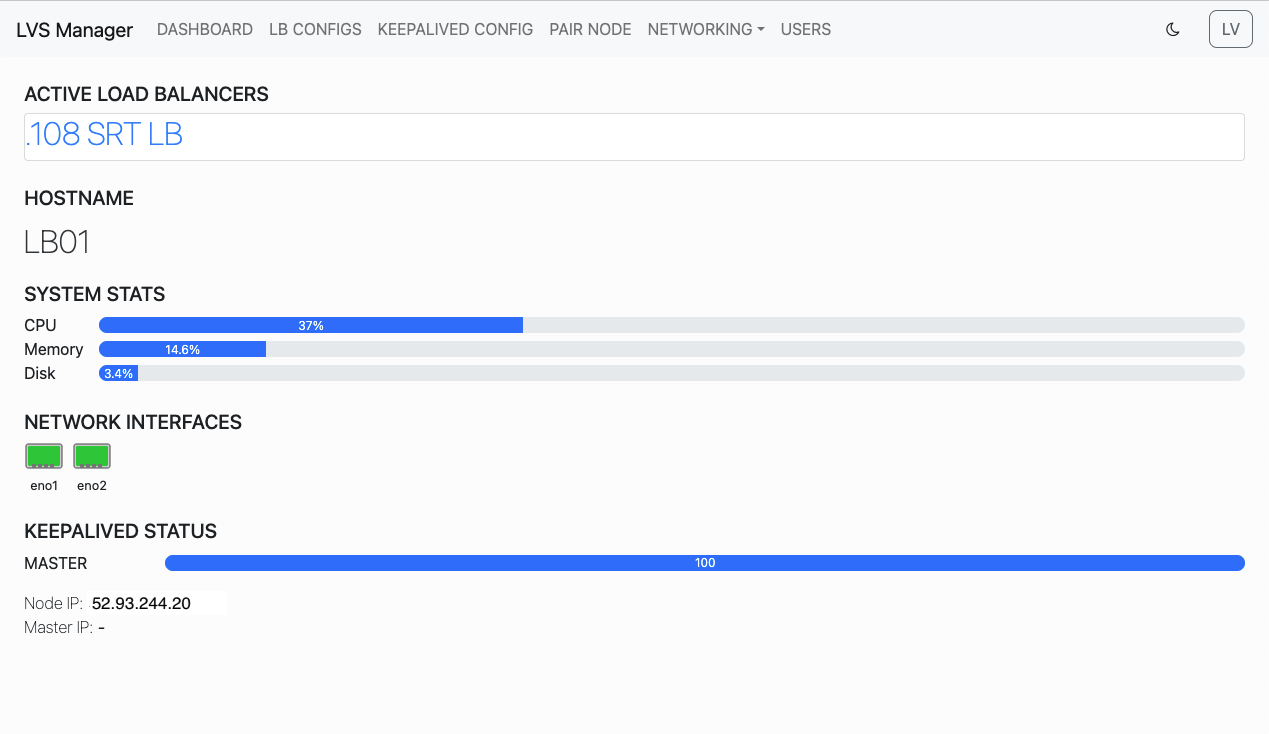
1. Dashboard Overview
Shows active load balancers and system status like CPU, Memory, Disk, and Keepalived.
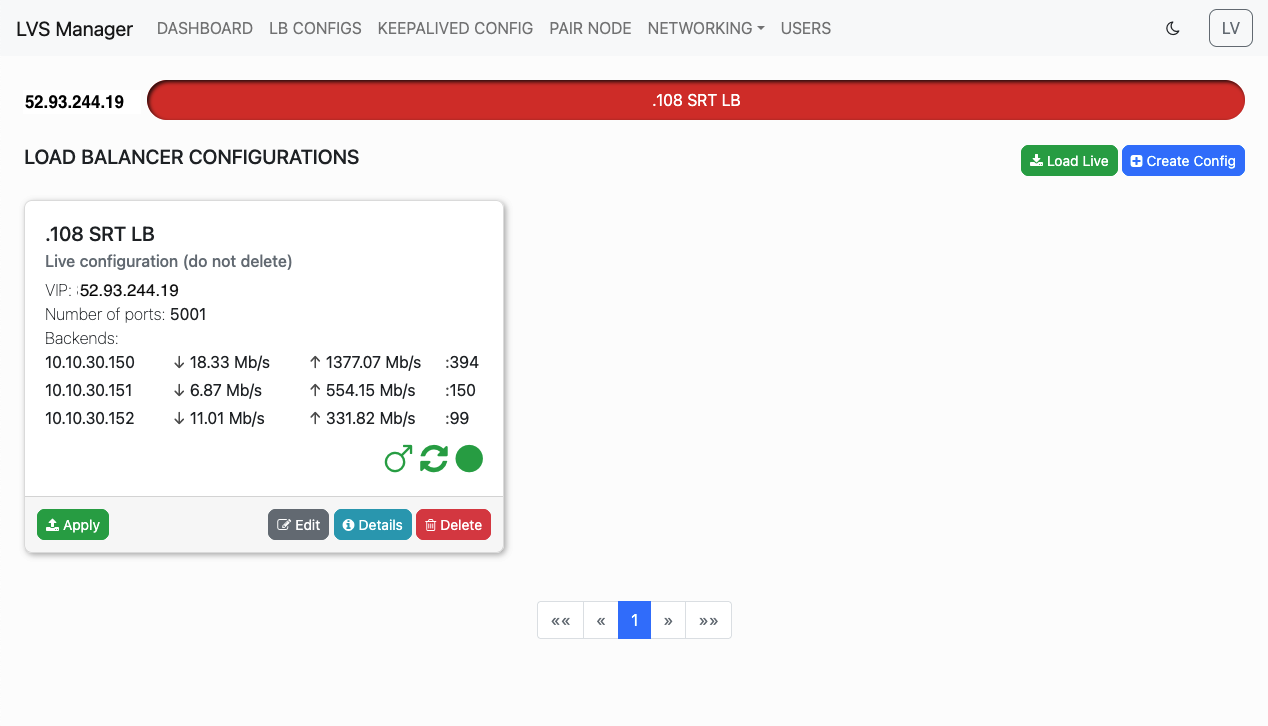
2. Accessing LB Configs
Navigate from the top menu to see all Load Balancer configurations.
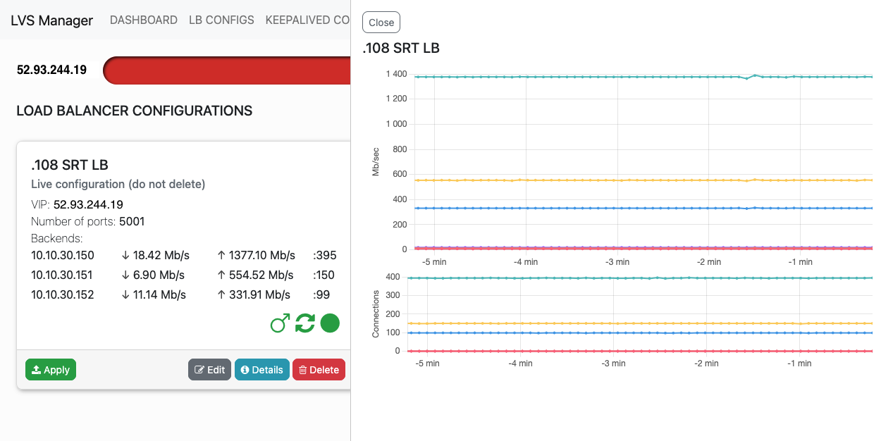
3. Rates history graph
Click the Rates numbers on a Load Balancer card to view current bandwidth and connection statistics graph.
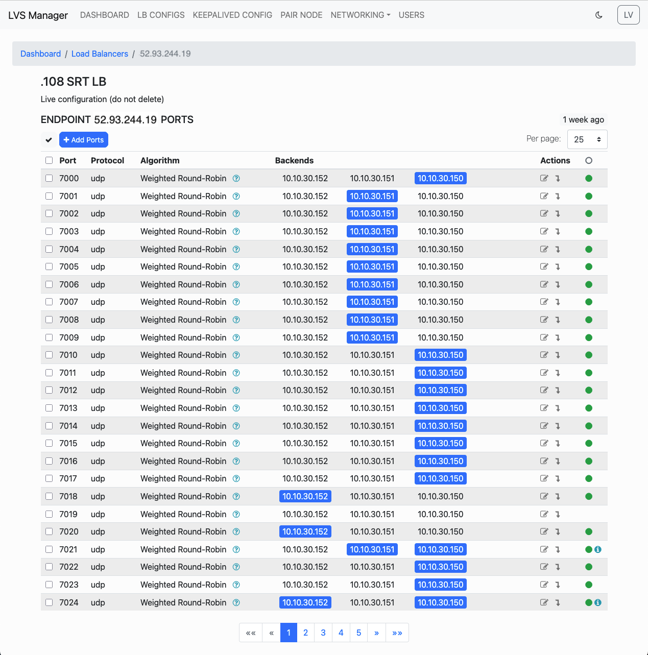
4. Configuration Details
Use the "Details" button to access editable parameters for port mappings, backends, and algorithms.
Configuration Management
Select All or Groups of Ports
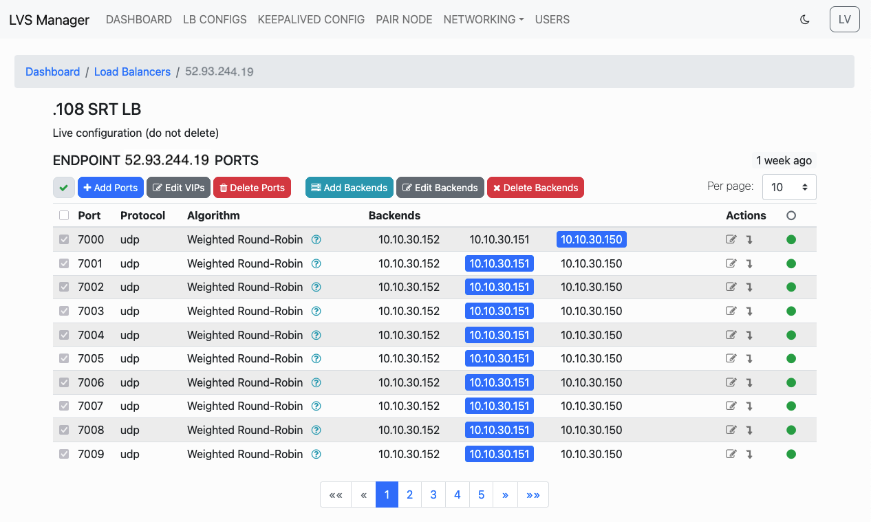
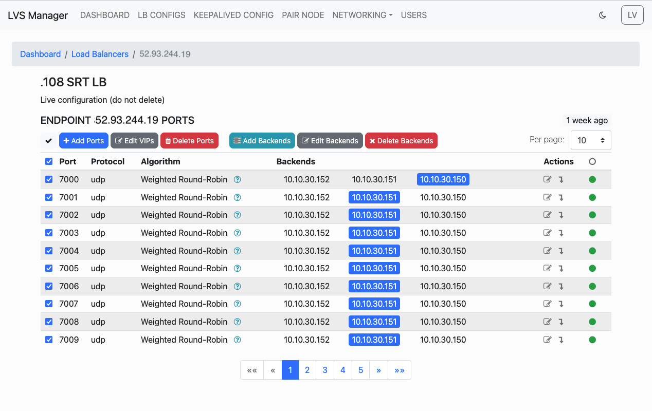
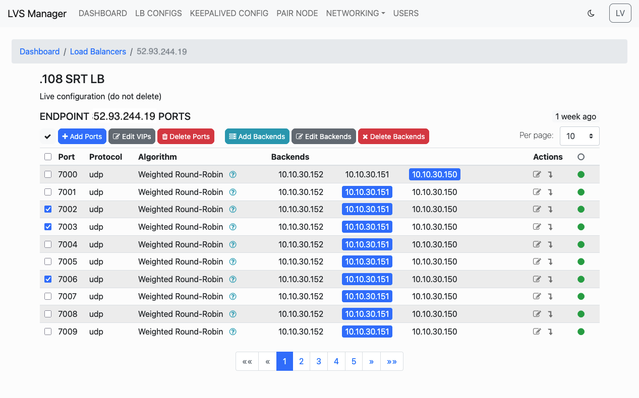
You can bulk-select visible or custom ranges of ports for editing.
-
All ports:
-
Visible ports:
-
Specific group:
Editing Backend Servers
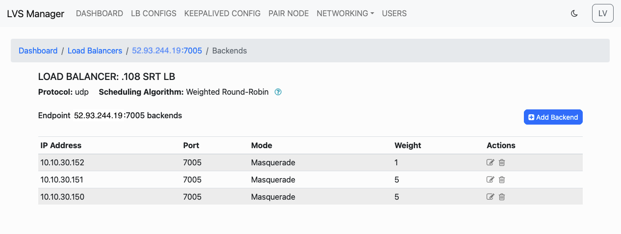
Access backend edit screen via dropdown per-port controls.
Live Monitoring & Statistics
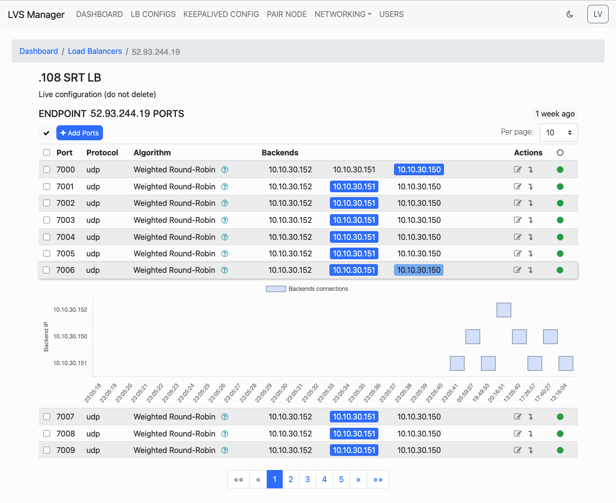
Real-Time Backend Switch
Hover over a backend IP to see if it available for swith to and click for switch traffic.
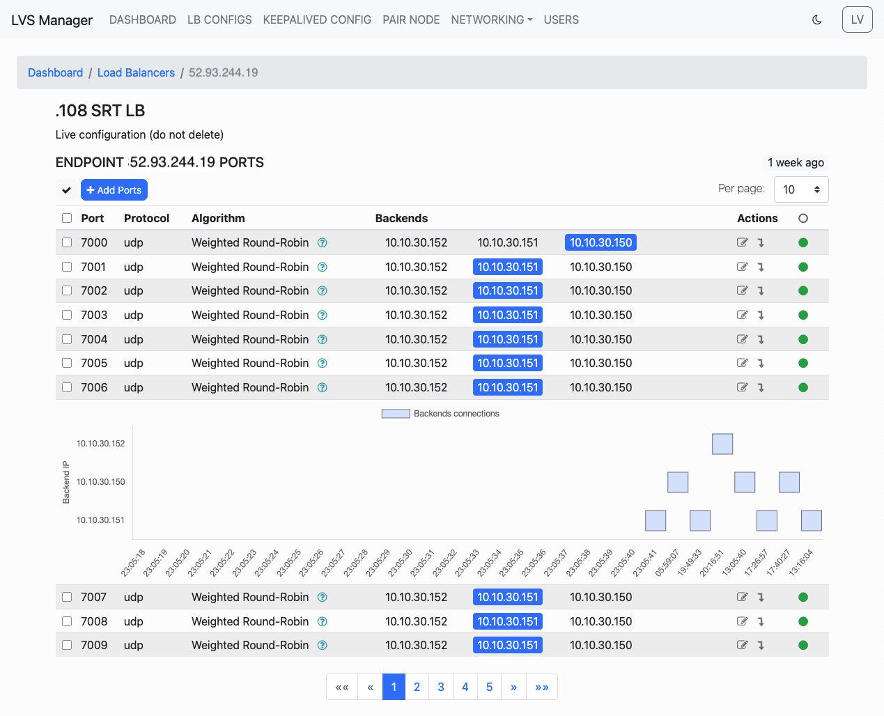
Connection History & State Events
Click the row to view the historical state changes and health events.
Creating a Load Balancer Configuration
To define a new Load Balancer configuration, follow these steps.
Step 1: Open the Configuration Page
From the LB CONFIGS page, click the Create Config button to open the Load Balancer creation form.

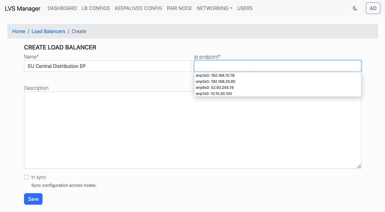
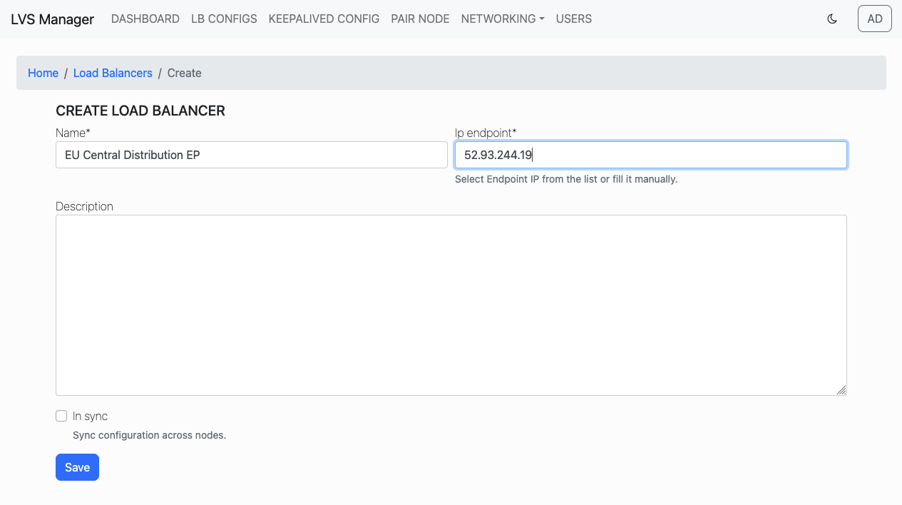
Step 2: Fill in Configuration Details
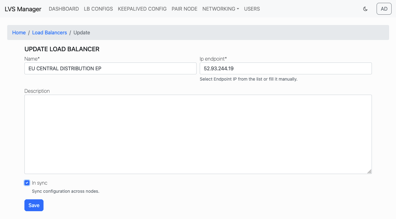
On the "Create Load Balancer" form, provide: - Name: a user-friendly name for your configuration. - IP Endpoint: the VIP to be exposed. You may choose from available interfaces or enter manually. - (Optional) Description: any notes for future reference. - (Optional) In Sync: enable if configuration should be automatically mirrored across paired nodes.
Step 3: Save Configuration
Click Save to create the configuration.
Step 4: View Result
The configuration will appear on the LB CONFIGS page with 0 ports by default.
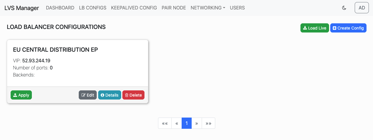
You can now proceed to add VIPs and backends to the configuration.
VIP (Virtual IP) Management
VIPs define the external ports exposed by the Load Balancer for client connections. LVS Manager supports single and bulk editing of VIP entries.
Add Ports
From the Configuration Details page, click the Add Ports button.
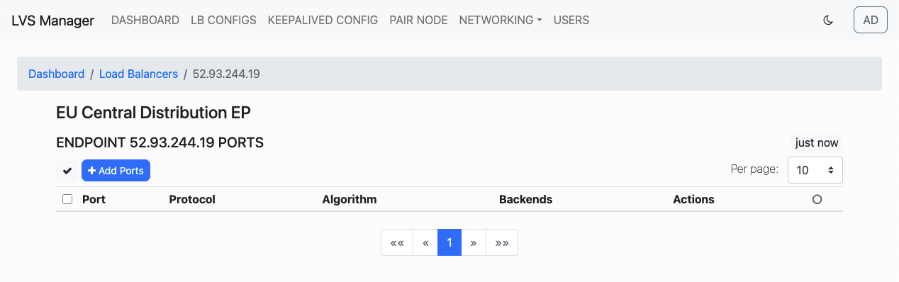
Specify: - Start Port and End Port: range of ports to add - Protocol: UDP is the only supported protocol - Scheduling Algorithm: choose how traffic is distributed
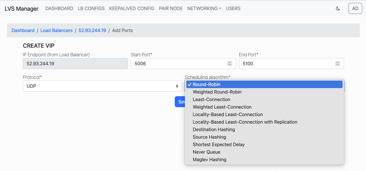
Click Save to create the new VIPs.
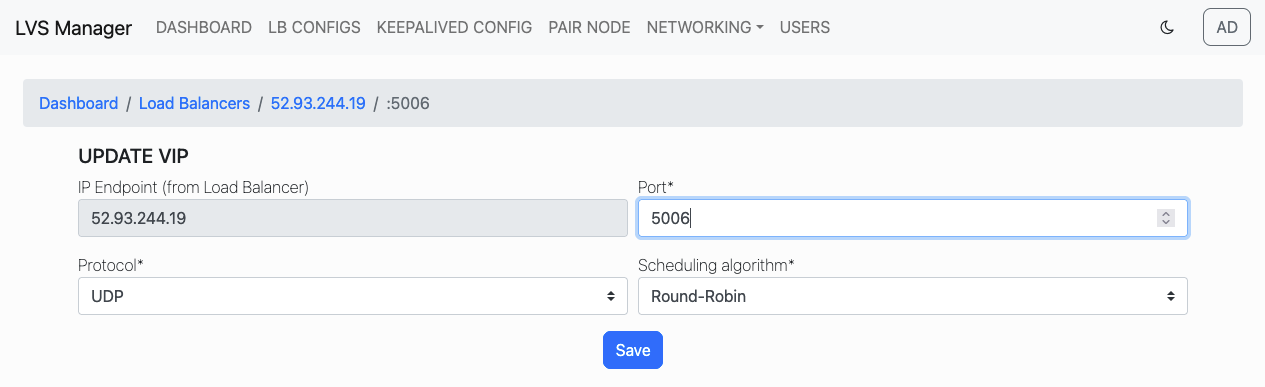
Edit VIP
Click the pencil icon next to a port entry to edit its configuration.
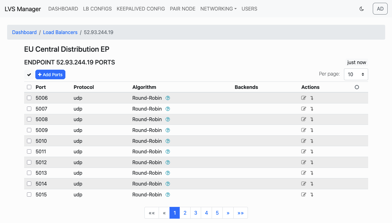
Change the port, protocol, or scheduling algorithm.
Bulk Edit VIPs
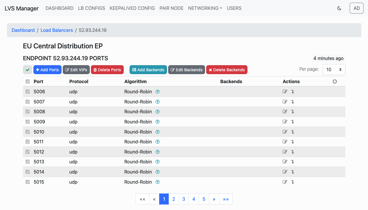
You can select multiple VIPs using checkboxes and apply changes in bulk.
-
Click Select All, Select All Visible or Select Certain to include all entries or all visible or certain selected.
-
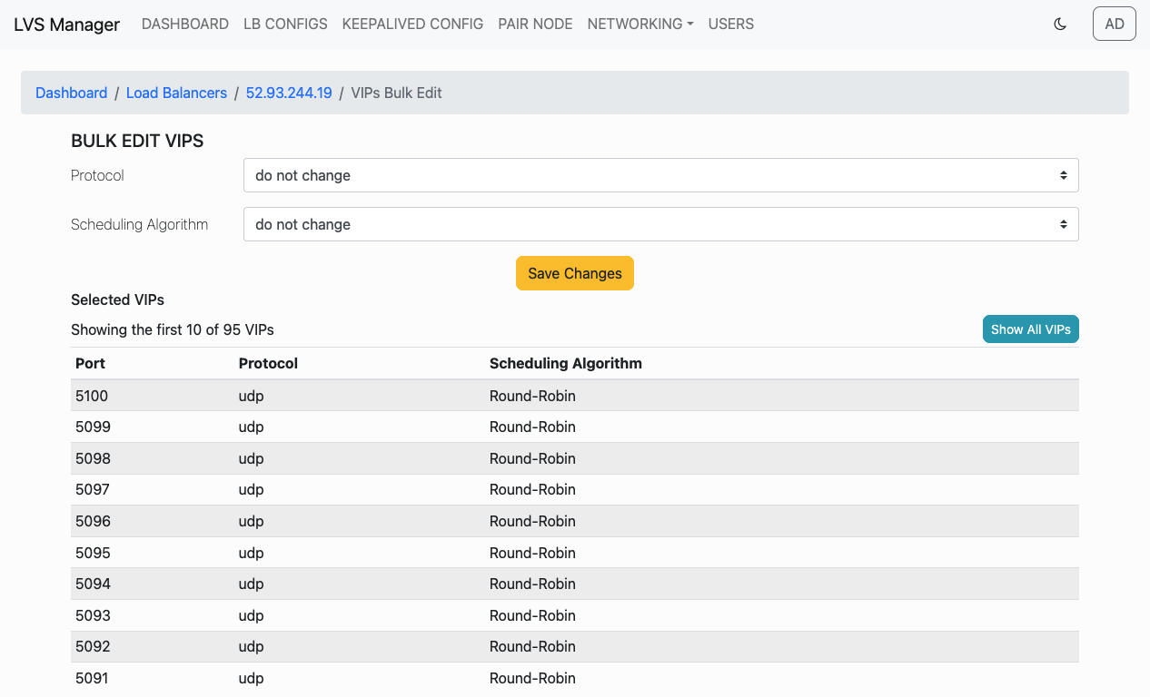
Click Edit VIPs:
-
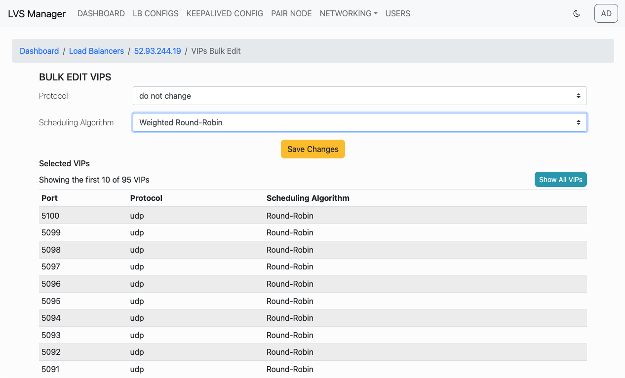
Update values (leave as "do not change" to skip).
-
Click Save Changes.
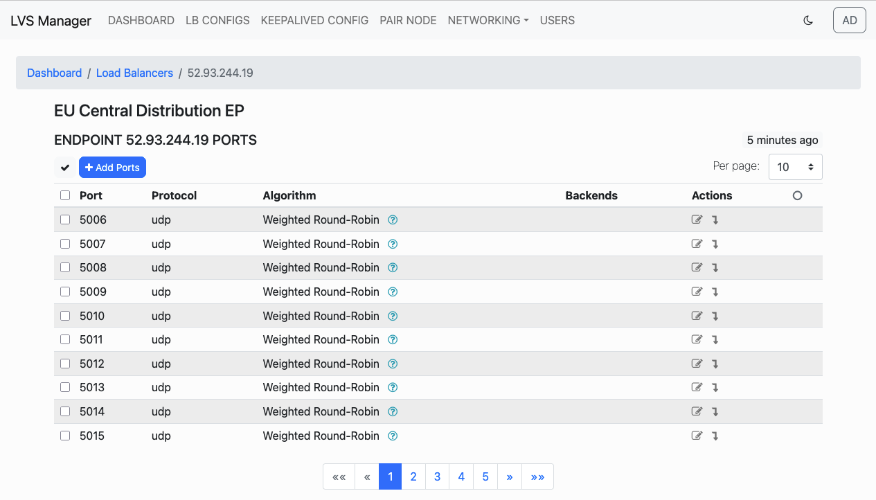
VIPs will be updated accordingly.
Bulk Delete VIPs
You can delete multiple VIPs (ports) in one action.
-
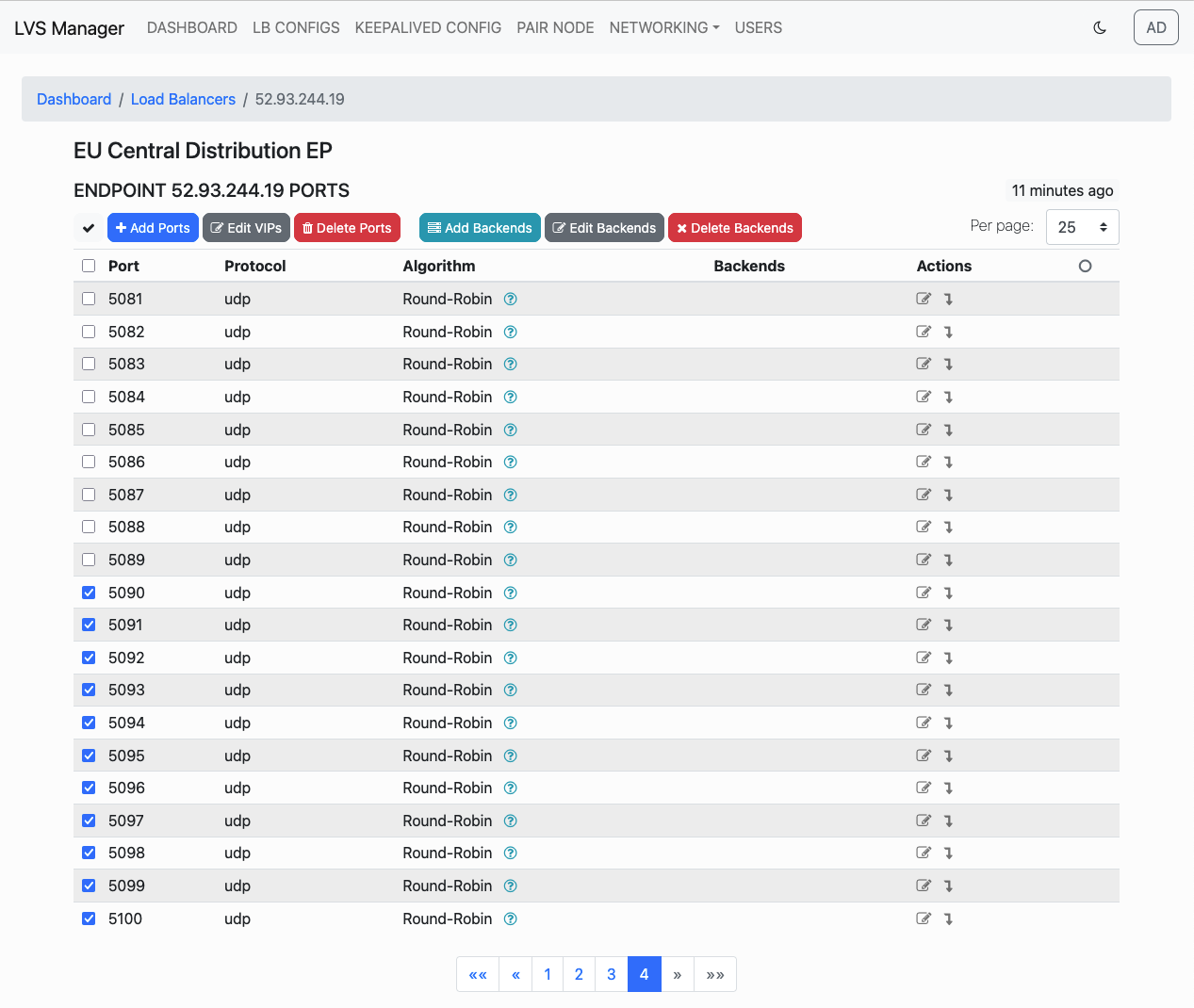
Select the desired ports to remove by checking the checkboxes on the left:
-
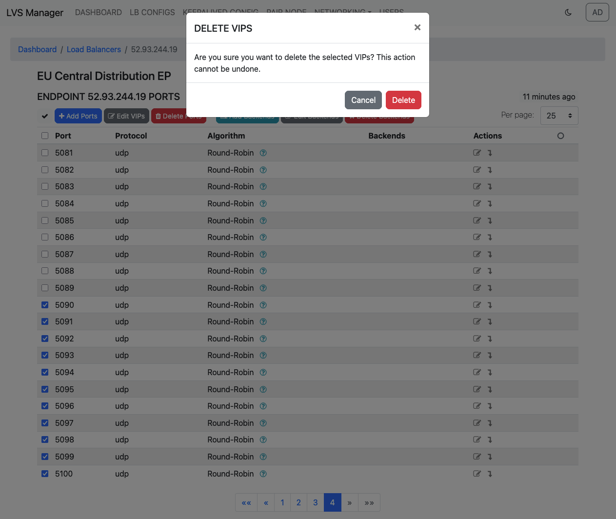
Click the Delete Ports button:
-
Confirm the deletion in the popup dialog:
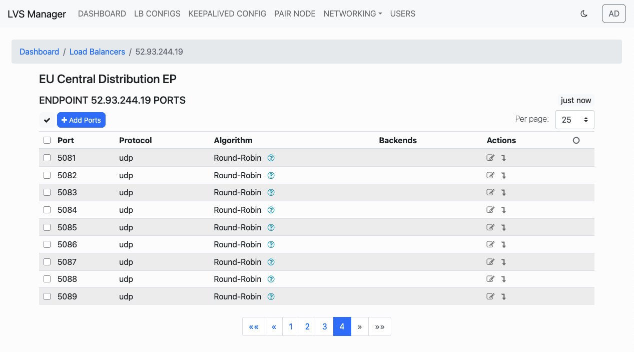
The selected VIPs will be permanently deleted.
Backend Management
Backend editing allows control over: - Backend IP - Port - Forwarding Mode (e.g., Masquerade) - Weight
You can edit each field or delete backends as needed via action icons.
Add Backends in Bulk
To add a backend IP address to multiple VIP ports:
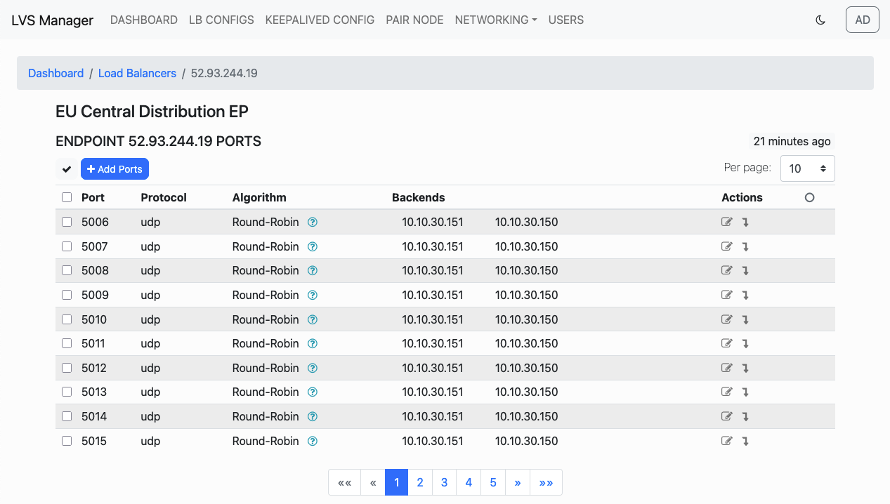
1. Select the desired ports on the configuration detail page.
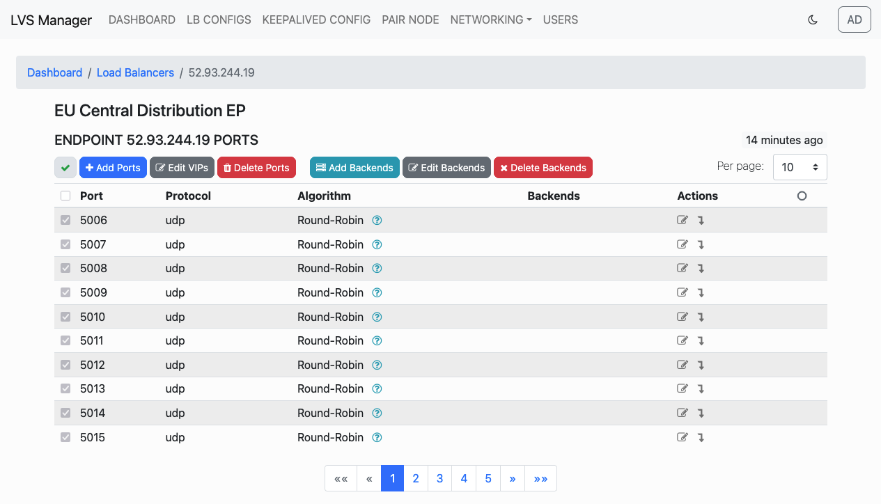 2. Click on the Add Backends button.
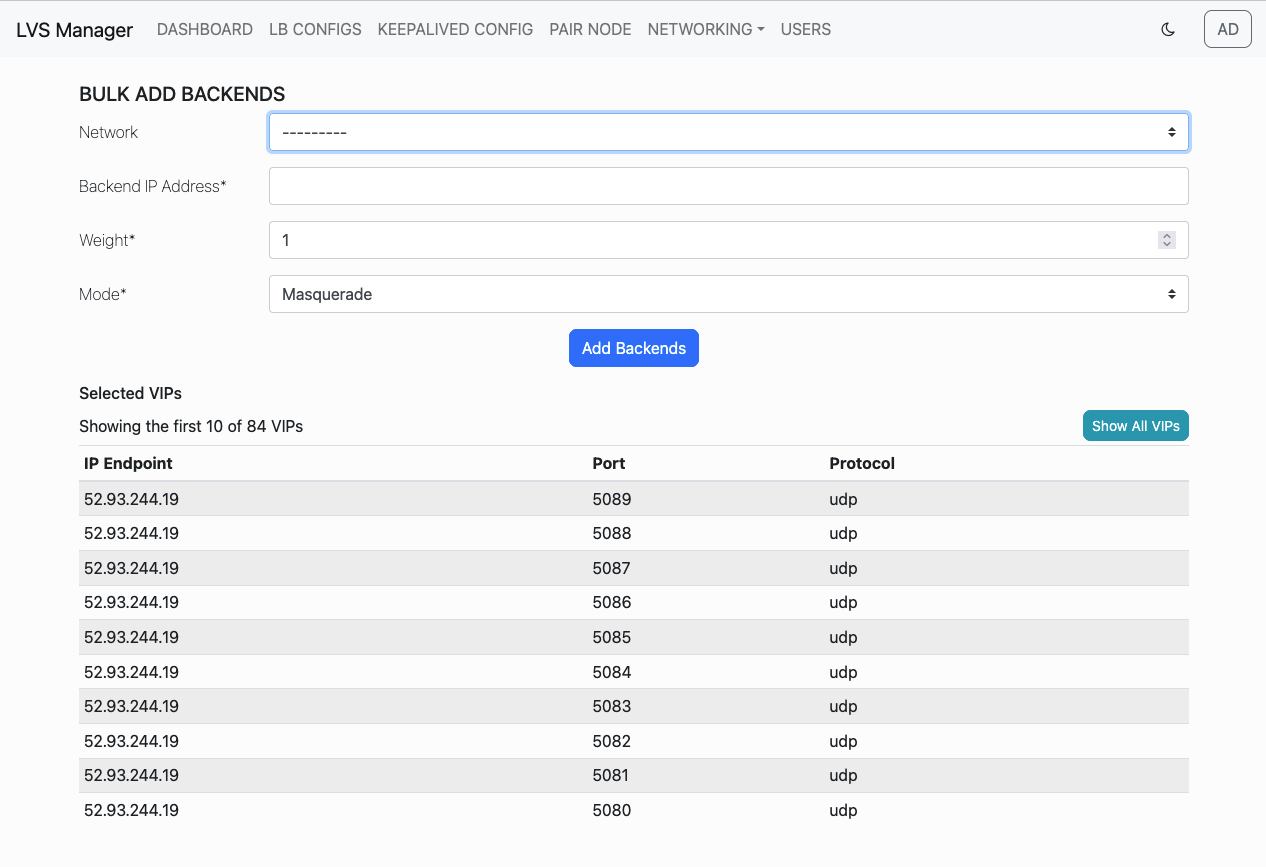 3. On the "Bulk Add Backends" page, select the appropriate network, enter the Backend IP address, set the weight and choose the routing mode (Masquerade, Tunnel, Route).
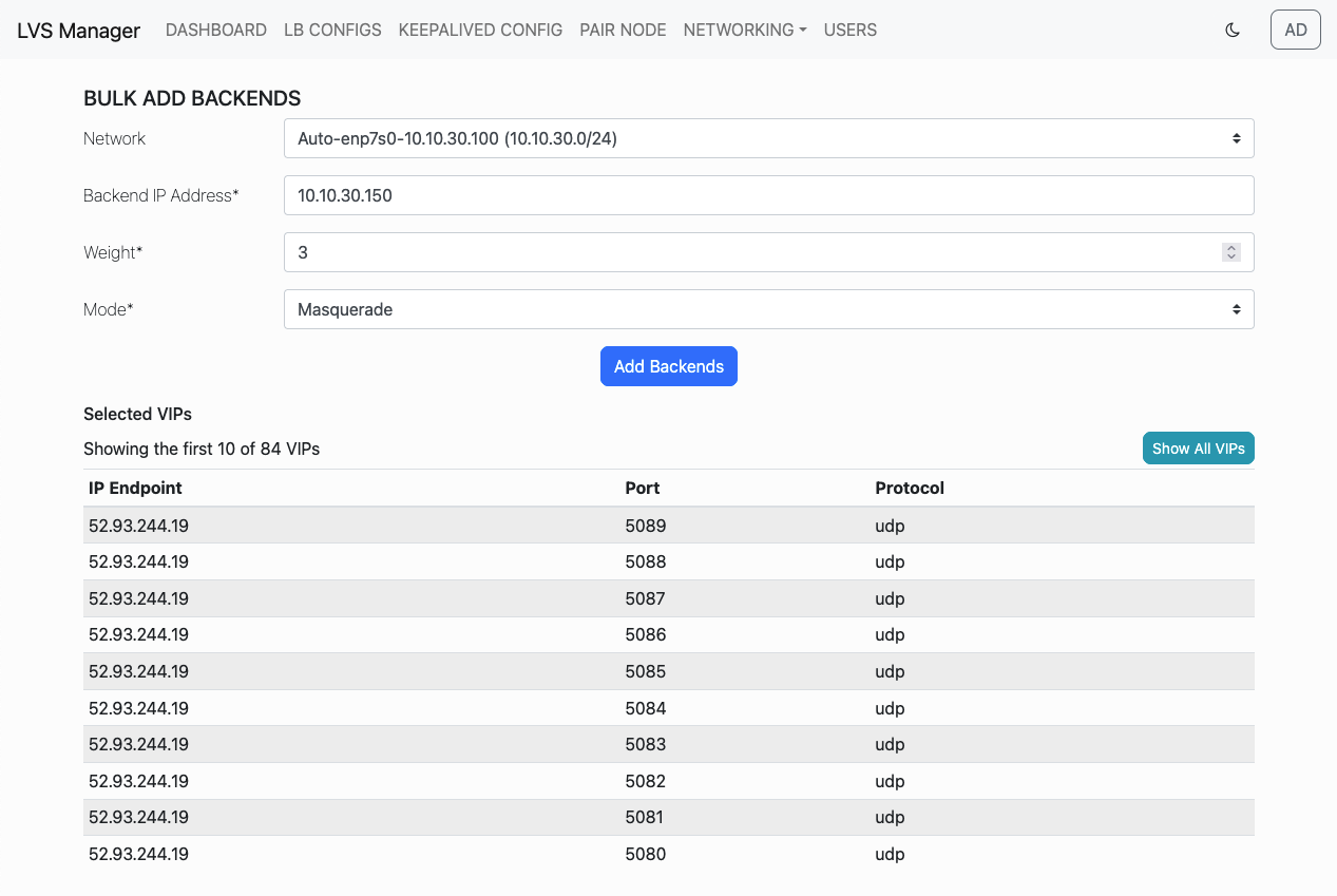 4. Click Add Backends to submit.
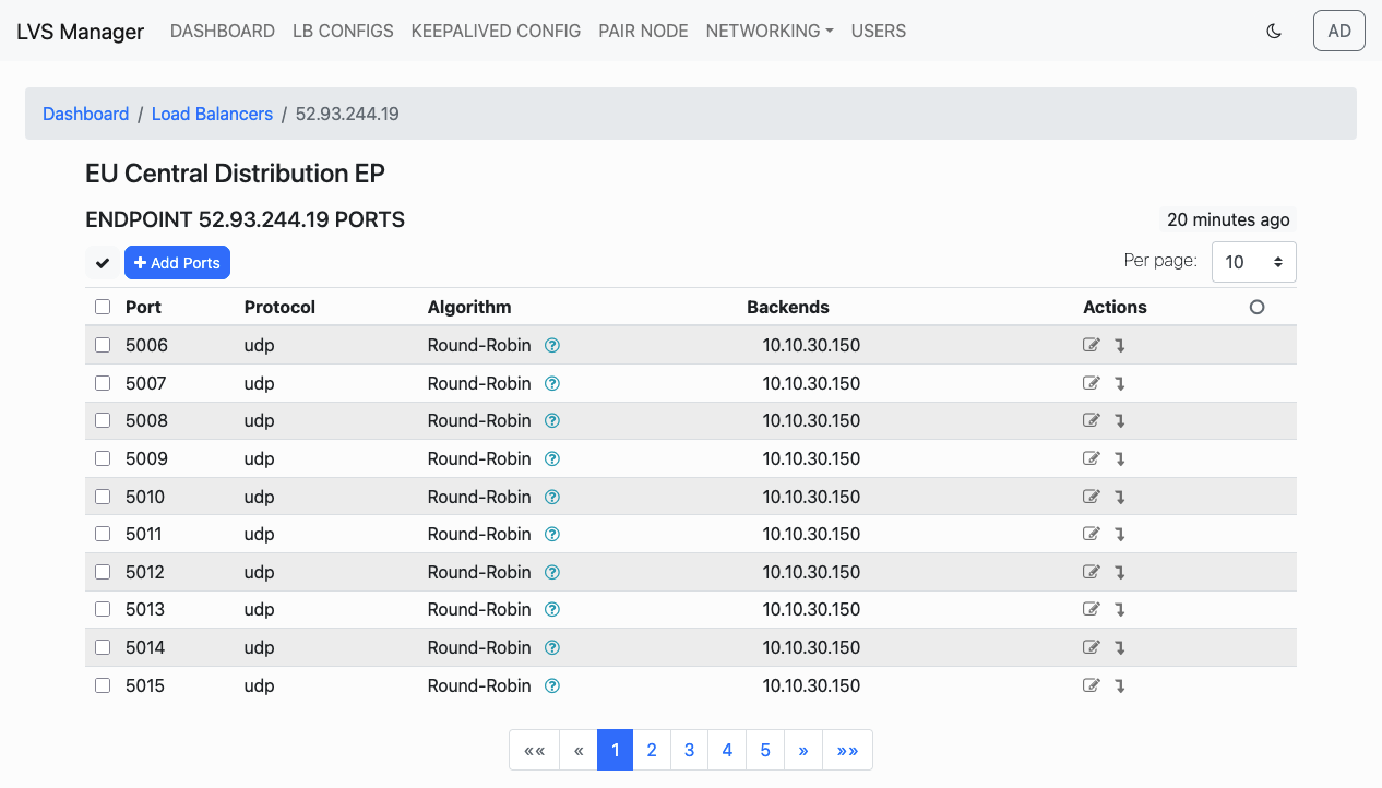 5. Repeat this flow if you need to add multiple Backend IPs.
Edit Backends in Bulk
To change the weight or routing mode of existing backends for selected ports:
1. Select the ports on the configuration page.
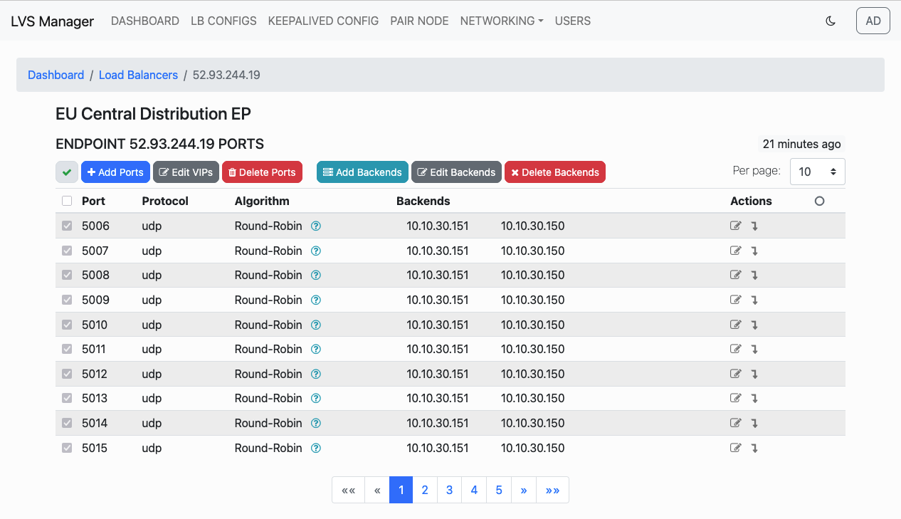 2. Click on Edit Backends.
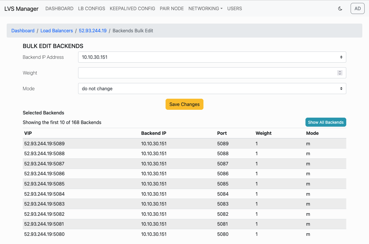 3. On the "Bulk Edit Backends" page, set the new backend IP address (optional), change the weight, and select the mode (or leave as “do not change”).
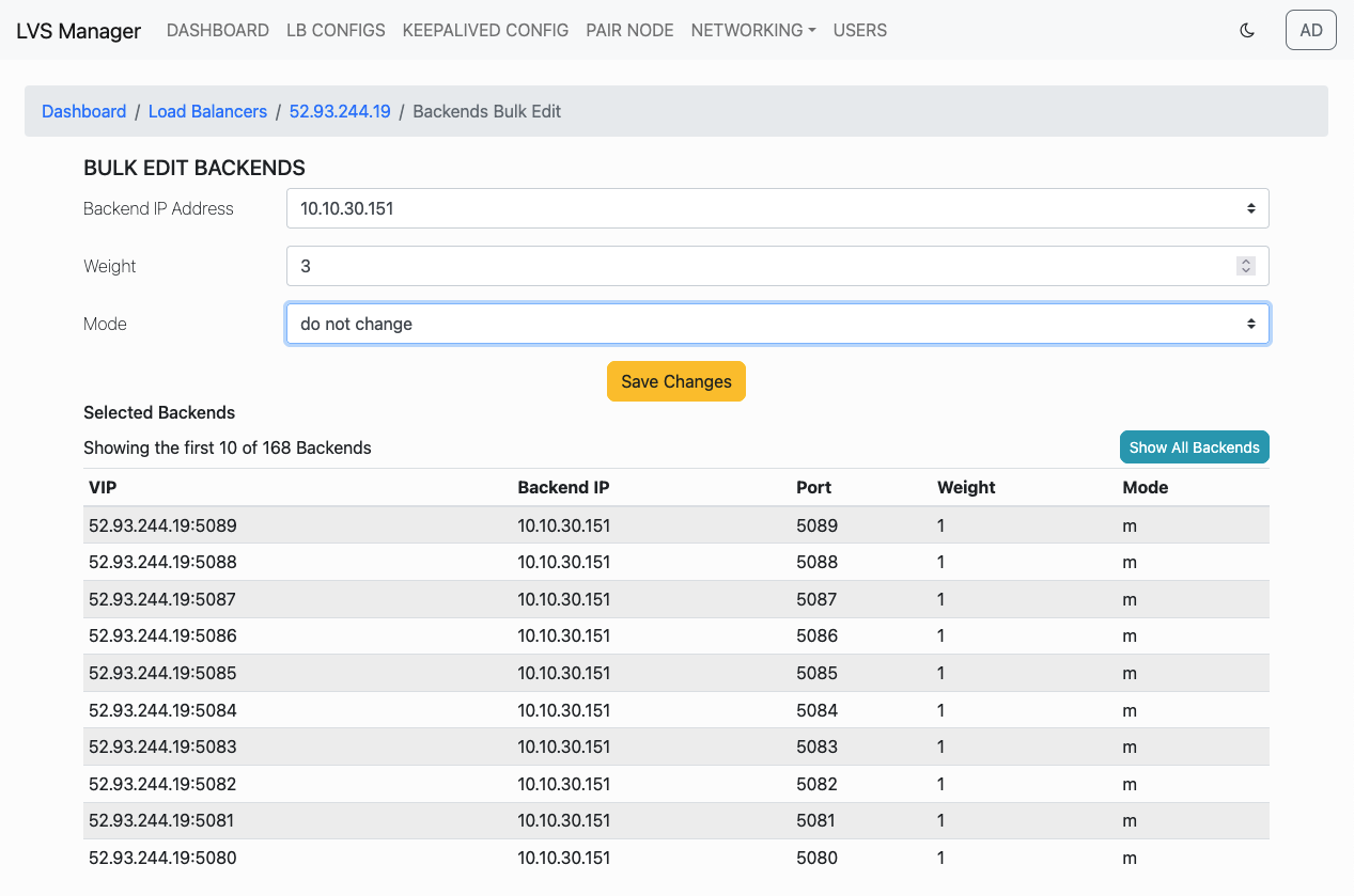 4. Click Save Changes and verify updated configuration.

Delete Backends in Bulk
- Select the ports whose backends you want to delete.
- Click Delete Backends on the top menu and select Backends has to be deleted from selected VIP ports.
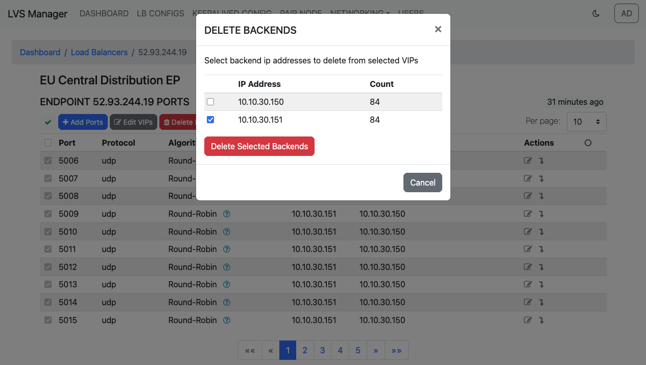
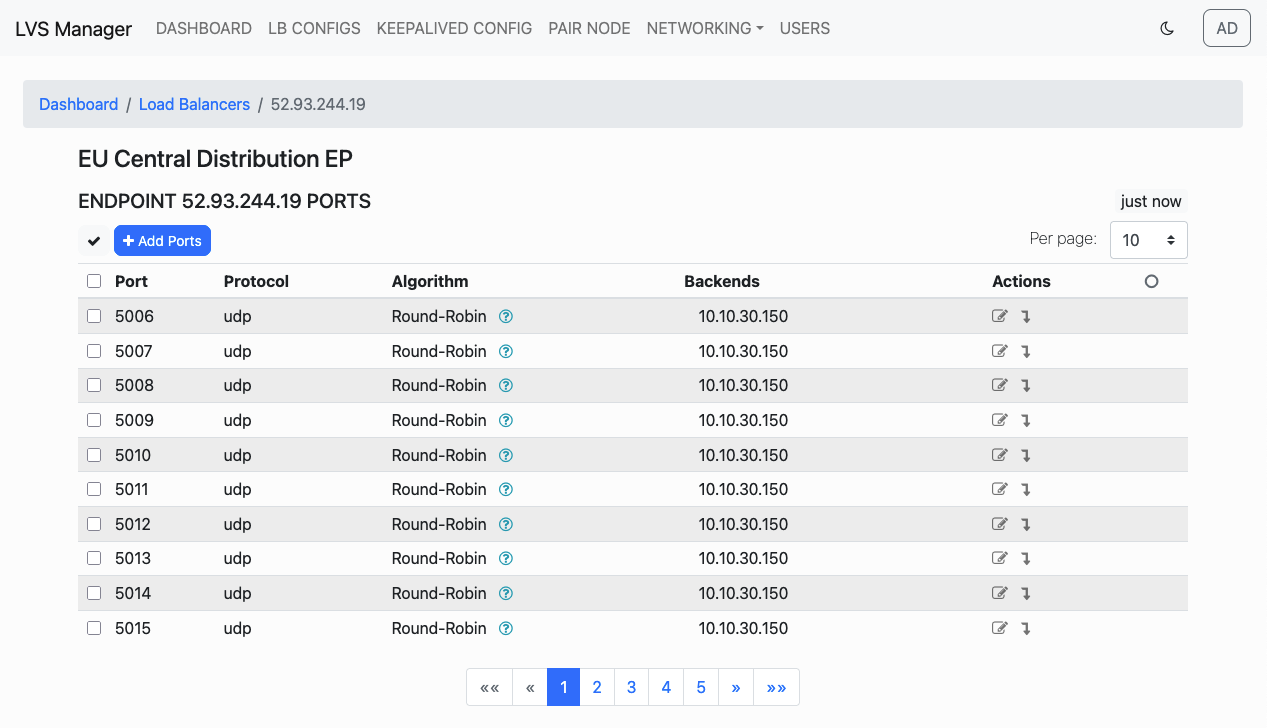
- Confirm the deletion. The removed backend(s) will no longer appear in the configuration.
Applying Configuration to Live System
Once your configuration is ready, you can apply it to the live system for activation.
Step 1: Create or Edit Configuration
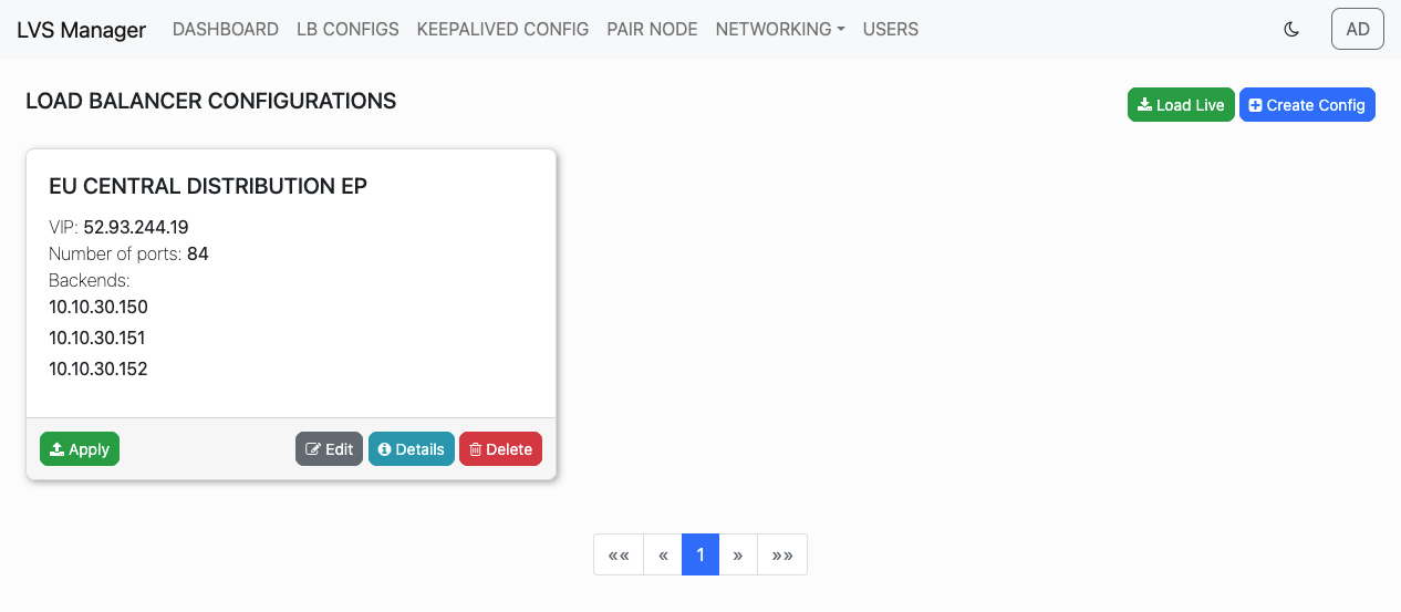
After editing or creating a new configuration, it appears in the list on the LB Configs page.
Step 2: Click "Apply"
Use the Apply button to push changes to the live LVS setup.
Step 3: Review Differences
A summary of changes what has to be applied will appear. This includes: - Additions (new VIPs, backends) - Updates (e.g., weights) - Deletions (removed routes) - IPTABLES rule differences
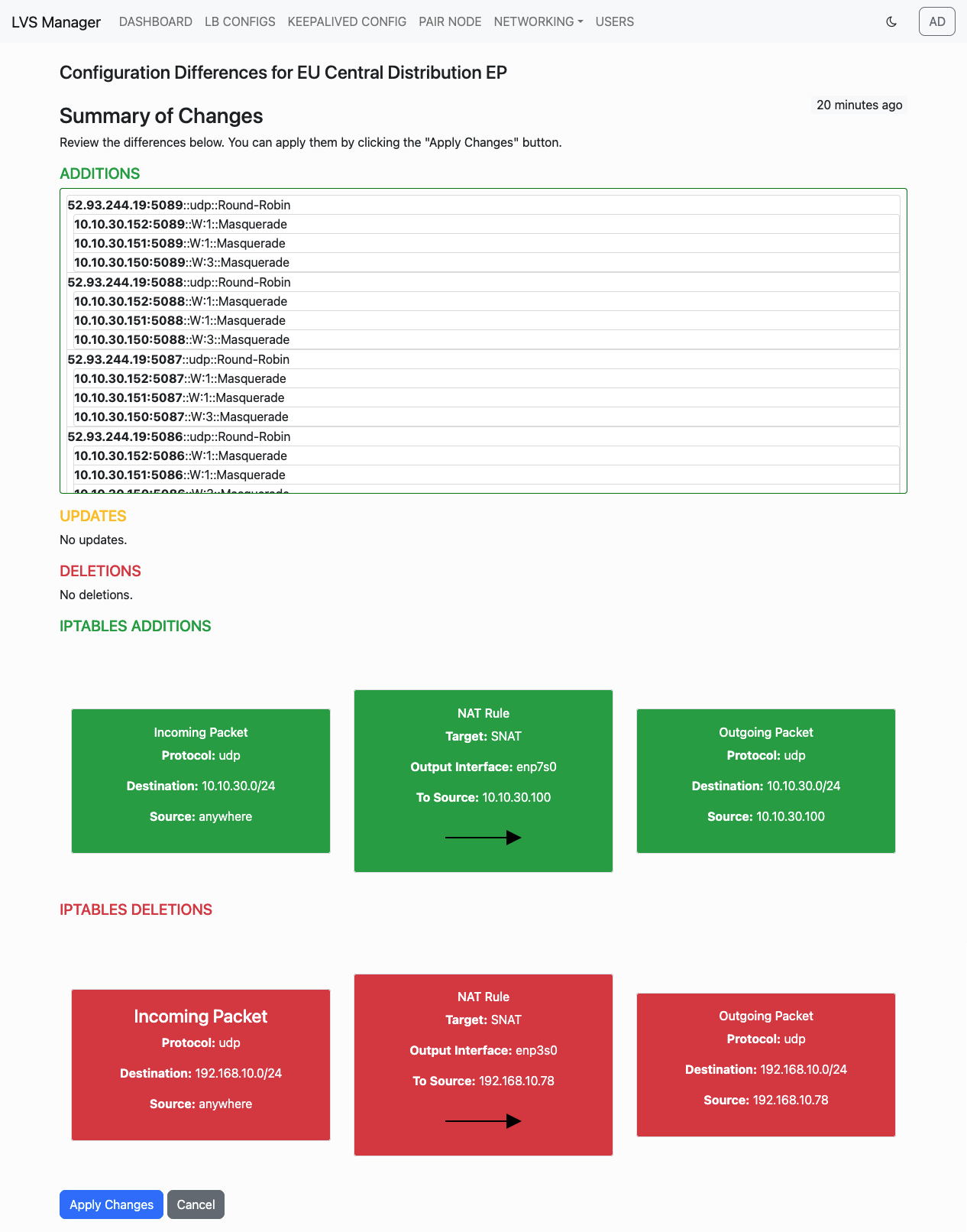
After review, click Apply Changes to complete the deployment.
Step 4: Live Configuration
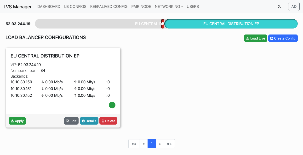
After successful apply, the timeline and statistics will appear on the configuration card.
Advanced Operations
Master/Backup Node Failover with Keepalived
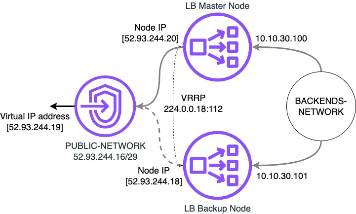
To provide high availability for VIPs, LVS Manager allows configuration of Master and Backup nodes using keepalived.
Here is an example of configuration scheme with master/backup operation.
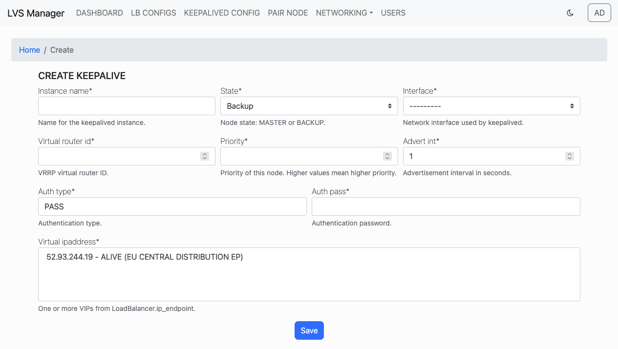
Step 1: Open Keepalived Config Page
Navigate to the KEEPALIVED CONFIG tab in the main menu.
Step 2: Create Master Node Configuration
Fill out the required fields to define the Master node:
- Instance Name: A user-defined identifier.
- State: Set to
Master. - Interface: Select the appropriate network interface.
- Virtual Router ID: Must match across nodes in the same failover group.
- Priority: Higher than the backup node (e.g., 100).
- Advert Interval: Usually set to 1 second.
- Auth Type: Authentication type (e.g., PASS).
- Auth Pass: Shared password between nodes.
- Virtual IP Address: Select one or more existing VIPs.
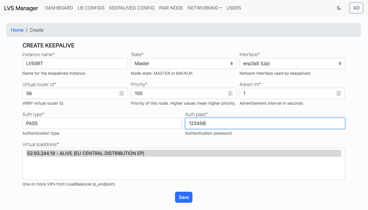
Click Save to store the Master configuration.
Step 3: Verify Master Node Configuration
You will see the configuration summary displayed.
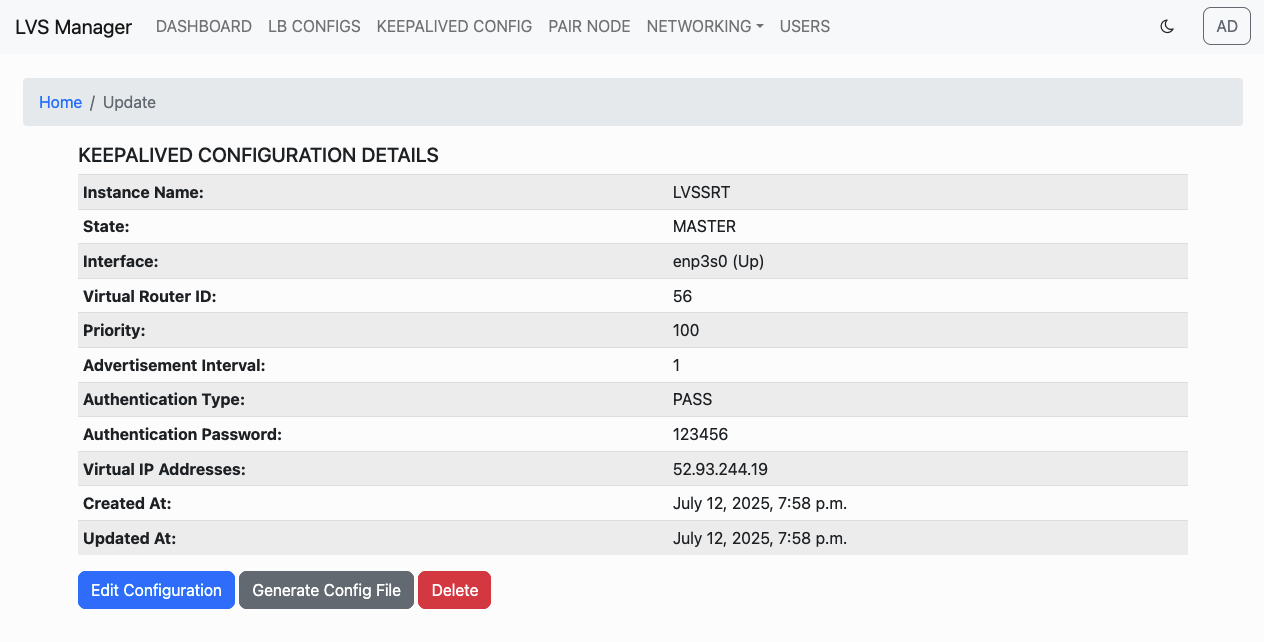
Step 4: Create Backup Node configuration
Repeat the same process, but set:
- State to Backup
- Priority lower than master (e.g., 90)
Make sure the Virtual Router ID, Auth Type, Auth Pass, and Virtual IPs are identical to the Master node.
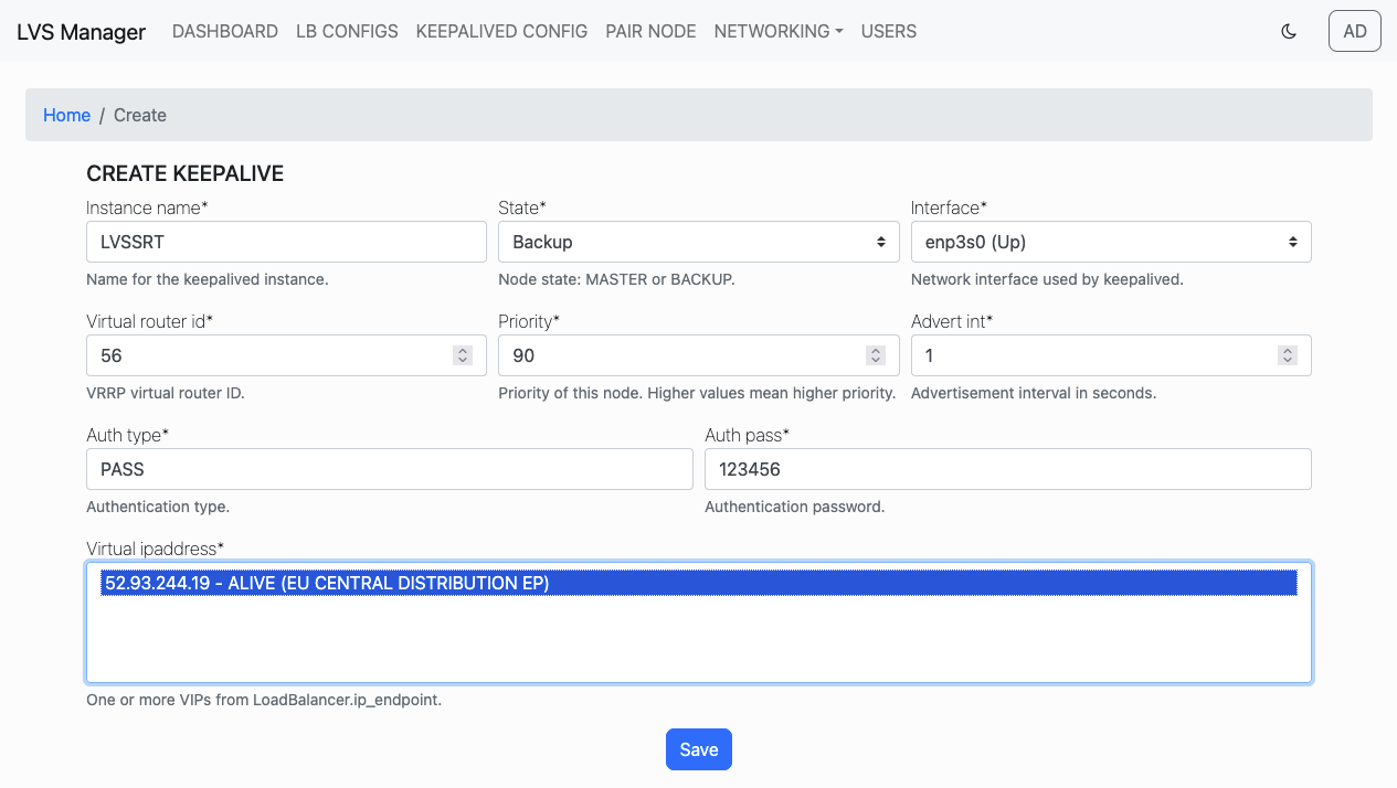
Click Save to finish configuring the Backup node.
When Keepalived is started on both nodes, VIP ownership will be assigned to the Master, and automatically transferred to the Backup if the Master goes offline.
Pairing Nodes for Configuration Sync
To ensure that configuration is always consistent across nodes, LVS Manager provides a node pairing feature. In this setup:
- The node in Master state is the source of truth.
- Backup node(s) follow the Master and are always overwritten with the latest applied configuration from the Master.
- Changes made on Backup nodes are discarded and cannot override the Master configuration.
- Only configurations that are applied on the Master node are synced, not drafts or pending edits.
Step 1: Expose Sync API
Navigate to the Networks page from the top menu.
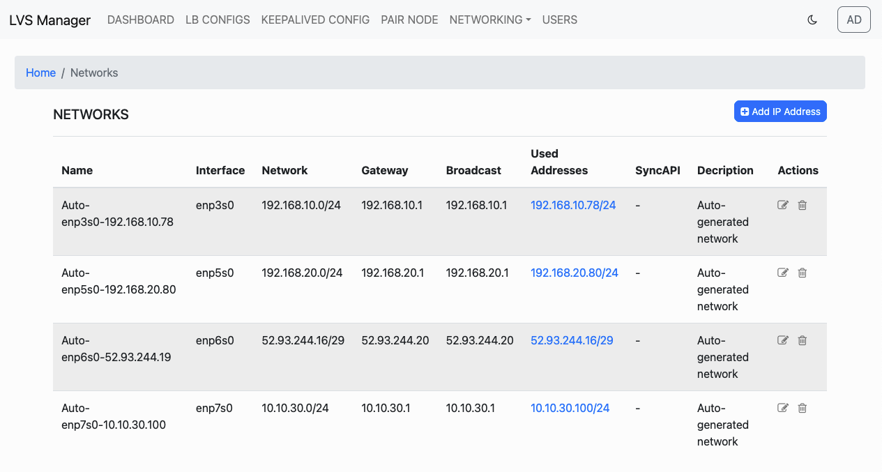
Edit the network of the Master node and check API exposed to allow pairing.
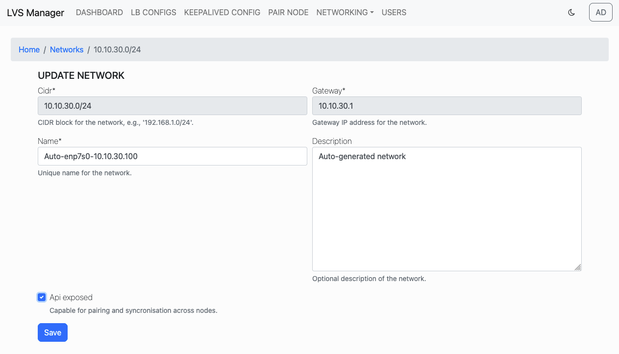
Once enabled, Sync API will be available:
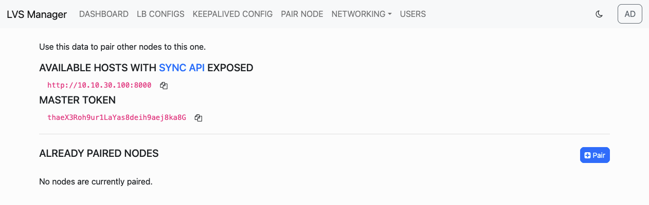
Step 2: Copy Master Node Information
Go to the Pair Node tab on the Master node.
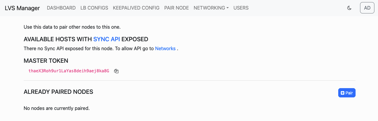
Copy the Sync API URL and the Master Token.
Step 3: Open Pair Dialog on Backup Node
On the Backup node, visit the Networks tab, and click the Pair button.
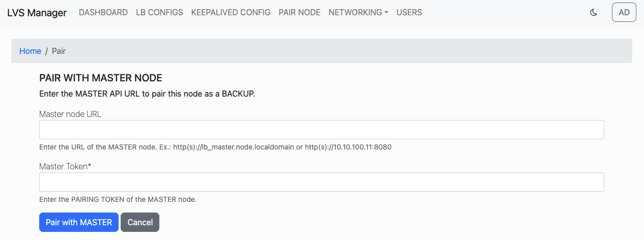
Step 4: Enter Master Node Details
Paste the Master URL and Token into the pairing form and click Pair with MASTER.
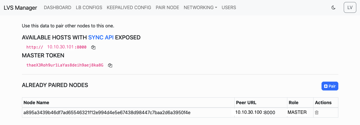
Once successful, the nodes will be paired and configuration from the Master will be propagated automatically.
Step5: Select configurations to be syncronixzed
Once configuration sync is setup choose LB configurations in Master node to be syncronized acros Backup nodes
Port Mapping Capabilities
LVS Manager allows mapping each exposed VIP port on the Load Balancer to different destination ports on backend servers. This is useful when backend services are hosted on different port numbers than the exposed ones.
Overview
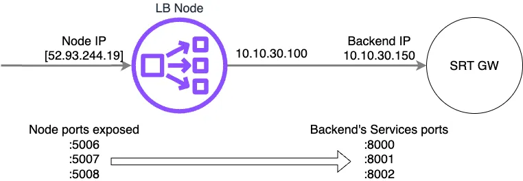
The diagram below shows a typical setup where:
- Node IP 52.93.244.19 (Load Balancer) exposes ports 5006, 5007, and 5008
- These ports are mapped to backend ports 8000, 8001, and 8002 respectively on 10.10.30.150
Step 1: View VIPs
From the configuration details page, all VIP ports exposed by the node are listed.

Step 2: Access Backend Editing
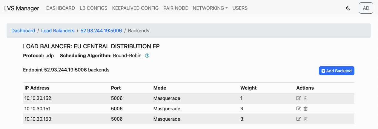
Click the arrow-down icon to edit backends for a specific port, such as port 5006.
Step 3: Override Backend Port
Use the Override port field to enter a different destination port for each backend server.
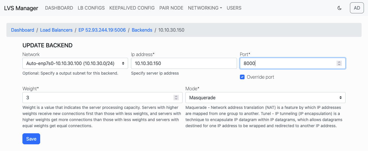
For example, map port 5006 to 10.10.30.150:8000.
Step 4: Verify Mappings
Once the port override is saved, the configuration page will reflect custom port values.
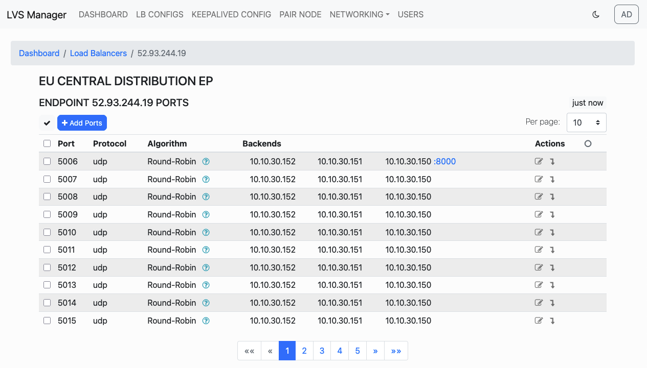
Each backend IP will include its target port if it differs from the default exposed port.